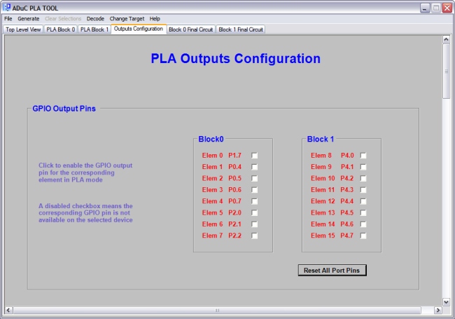
The image above shows the first panel on the output configuration tab. This panel allows the user
to select which GPIO pins will be enabled in PLA mode. If the user's design does not require the output of each element to
be available on a GPIO pin they can make a custom selection by clicking only the elements required. Once an element's checkbox is checked
code will be added to the Assembly or C file to enable the corresponding port pin in pla mode.
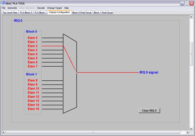
The next image shows one of 3 special output panels. These are the IRQ0, IRQ1 and ADC selection panels.
They allow the user to apply the output of one of the 16 elements to one of these signals.
Only one element output can be applied to any one of the muxes at a time. The
same element output may however be applied to more than one mux. For example a
user may choose to apply the output of element2 block0 to both the irq0 pin and
at the same time to the adc_st_conv pin. Each panel contains a button shown bottom right, this
allows users to clear selections on the individual muxes without erasing all selections.
As mentioned previously the outputs of all 16 elements are also available via the PLADOUT register.