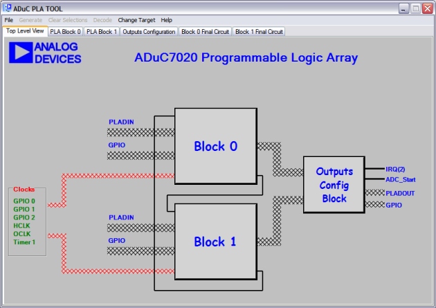
The image above shows the PLA Tool main window as the user sees it when it is first
launched. The Top Level tab presents a high level view of how the PLA hardware
is organised. We can see block 0 and block 1 and the interconnection between
them. Both blocks take inputs from the PLADIN register and the GPIO pins. Also
connected to the blocks is the clock source line. Each block has its own internal clock
mux which allows the user to apply different clock sources to the two blocks.
Also shown is the outputs configuration block. Within this block the user can
decide where to connect the outputs from the elements of the PLA.
The user should note that some options on
the main menu are disabled while the top level tab is selected. For example Generate is
disabled as no circuit design has occured yet and so no hex values or code can
be created.
The following sections describe how to begin designing circuits.