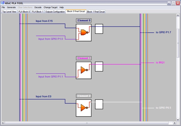
The aim of the final circuit tabs is to allow the user to review the main bulk of their circuit design before generating code or hex values. The tabs accomplish this by presenting the user with a stripped down, bare bones images of blocks 0 and 1. In stripping back the blocks the tabs remove all buses, clock lines and uneccessary connections to reveal only the active inputs, the lookup table showing the chosen function, whether the output is clocked or not and finally where the output of each element is available.
As can be seen in the image, colour coding is used to make distinquishing where inputs are taken from more obvious. The multi-colored bus represents
the heavy black lined bus present in the block 0 and 1 tabs. The user is free to modify designs in block 0 and 1 and the changes will automatically be mirrored on the final circuit tabs.
The following sections show some the special features of the PLA Tool, namely the Register Window, Code Window and Decode Window.