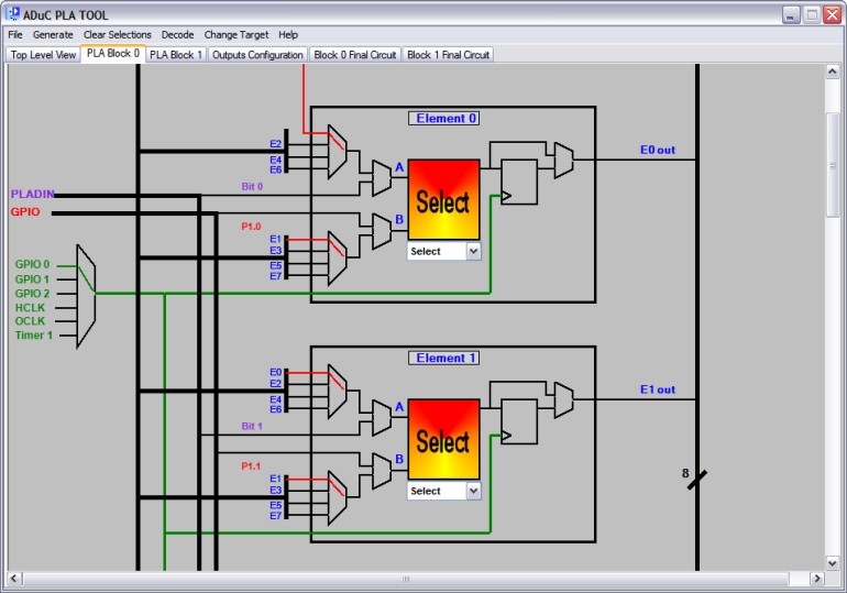
The above image shows the top section of the Block 0 tab. It shows two of the block's 8 elements and several surrounding connections. The structure and layout is identical for both blocks, which can be seen by quickly switching between tabs. When either block 0 or block 1 are selected all of the PLA Tool's options are available.
The first thing to note is the heavy black line on the image's outer edges which surrounds both elements (and indeed all 8 elements).
The line is broken every so often by a diagonal line accompanied by a figure 8. This is to signify that this line is in fact a bus.
The image shows that the output of each element is connected to this bus. If you follow the bus around you can see that each element takes 8 inputs from
the bus. Element 0 of each block happens to be a special case which will be explained later on. This arrangement sets up a feedback loop which ultimately allows
the user to interconnect up to all 16 elements in a circuit design.
Also visible are two vertical black lines running parallel to the elements' left hand sides. These are labelled as the PLADIN and GPIO buses. Each element
takes 1 input from each of these buses. In terms of the pla the PLADIN bus represents the 16-bit PLADIN register. The value written to this register is then
available on the inputs to the elements e.g. the value in bit 0 of the PLADIN register is available on the input to element 0 block 0 and so on. Each element also
takes an input from the GPIO pins interface. A complete list of which pins are connected to the 16 elements can be viewed by clicking
here.
Examining the individual elements you can see that that the first two muxes take four inputs each as described in the section on elements.
The user simply clicks on the input from the element they require and it becomes highlighted in red to indicate it is the active input at that mux. Input 0 of element 0 in each block has
special significance. In the case of block 0, input 0 to element 0 comes from the output of element 15 in block 1 and similarly input 0 to element 8
in block 1 comes from the output of element 7 in block 0. It is this arrangement that allows both blocks to be connected.
The next set of muxes, mux A and B, each have two possible inputs. The user can select, by click on the desired connection, the output of the initial "feedback muxes" or the input from either the PLADIN or GPIO bus.
Clicking on an active connection will disable it again. Once these selections have been made the outputs of mux A and B are available as inputs to the lookup
table.